.
.
| Engine Room |
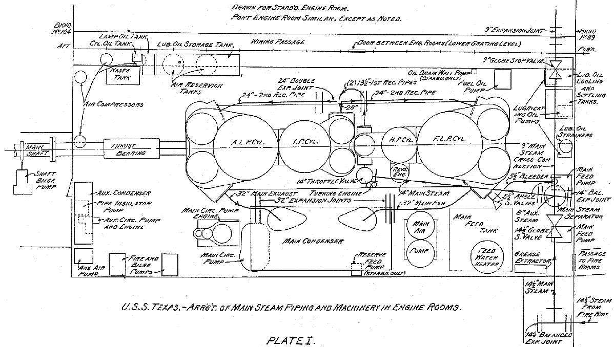
| TEXAS was propelled by two steam powered engines being triple expansion/dual
action with each connected to it's own propeller and no reduction gears.
The engines sailed the ship 728,000 miles |
| February 1914 Journal of the American Society of Naval Engineers |
 |
| "USS TEXAS (BB35) Ships Data 6", 1976, by Leeward Publications |
 |
| Propulsion History |
| The original propulsion drawings 29 September 1910 was
for one turbine with four propeller shafts, which was the ARKANSAS design, shaft
horsepower 32,000 (about 4,000 more then reciprocating engines) at rpm 330 vs
125 for reciprocating. By early December 1910, before the contract was issued,
the USN changed propulsion specifications to reciprocating engine. The change
was due to the fuel efficiency of the turbine at lower speeds being much less
efficient than the reciprocating engine. The engines in TEXAS and NEW YORK were the largest installed in a USN battleship. During the October 1913 sea trials off Rockland, Maine, the ship's fastest recorded speed was 22.28 knots (25.25 mph) at steam pressure of 274psi. During the USN period, at 125rpm, at steam pressure of 265psi, max speed was 21 knots in 1914 and 20.5knots in 1945. (I do wonder about the 265psi steam pressure for NEW YORK had 280psi and max speed.) By 1923, the navy looked again at installing turbine in TEXAS. Drawings were made to locate the turbines in boiler room and relocate the boilers outboard of the turbines. When the ship underwent modernization in 1925-1927, the engines were not modified. The engine room itself is largely unchanged from 1914. |
| Engine Operations |
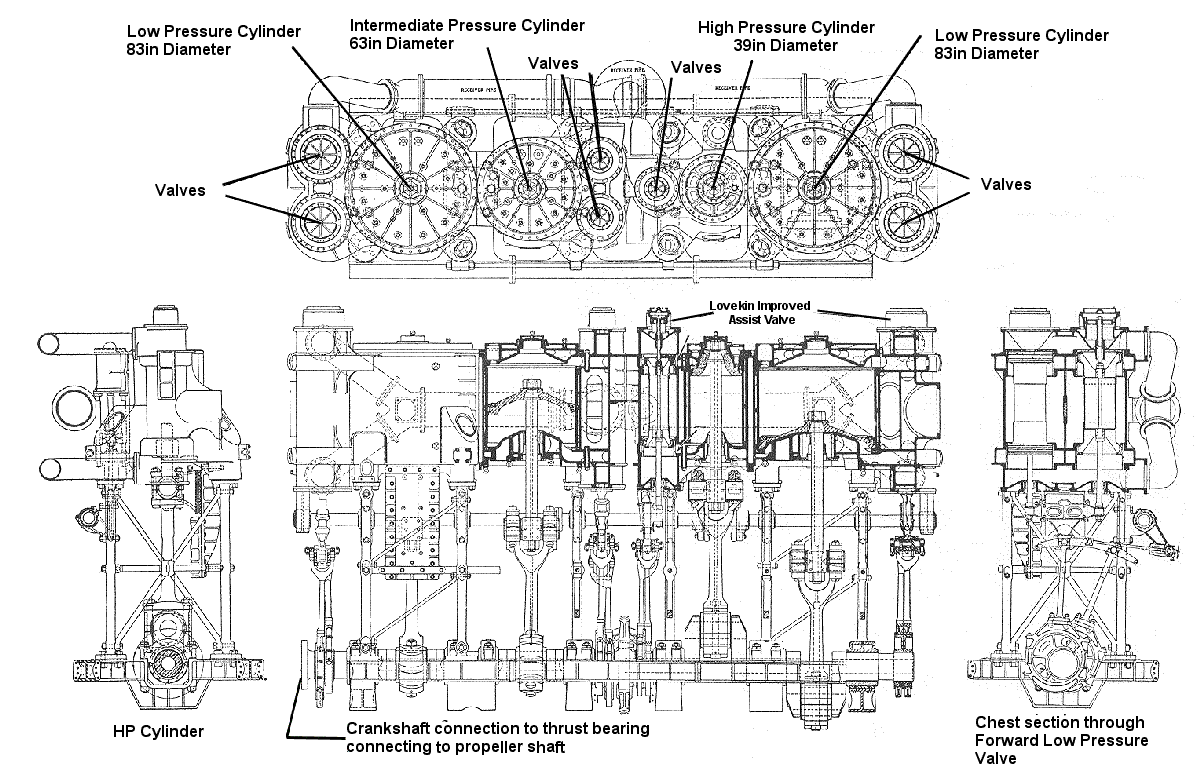
| Steam entered the engine at 265psi and flowed
through three increasingly larger diameter piston cylinders (triple expansion);
one 39inch high-pressure, one 63inch intermediate-pressure and two 83inch
low-pressure. (Some ocean liners had quadruple expansion engines). While the
steam pressure decreased as it went through each cylinder, the lower energy was
offset by the increased area of piston surface for the steam to expand on. When
both low pressure pistons filled with steam, the volume of steam had expended to
10.6 times the original volume that entered the high pressure cylinder. Engines are one-stroke (dual action): Unlike a four-stroke car engine or a two-stroke motorcycle, BB35 engines were one stroke. Each up and down movement of the pistons was a power stroke because steam entered on the top and bottom of the pistons. During a power stroke, the steam on the opposite side of the cylinder was exhausted to the next cylinder (or the condensers if at the low-pressure cylinder). 48 inches is the length of the engine stroke. When the steam was exhausted from the low pressure cylinders, the pressure was below atmospheric and had to be evacuated with a pump to the condenser which is outboard of each engine, against the outboard bulkhead. Cold saltwater circulated through the condenser to convert the warm steam to fresh water, which was then pumped into fresh water feed tanks for use by the boilers to make steam that goes back to the engines. Cutting off steam: To perform maintenance on the engine, all steam is cut off. To cool the engine at an even rate to prevent warping, the engine is mechanically rotated with the jacking gear. On the crankshaft is a large brass toothed gear. A worm gear intersects with the brass teeth with the worm gear shaft being connected to a 15hp motor, through a series of reduction gears. According to data on a BB35 drawing, one rotation of the crankshaft takes about 7.5 minutes Starting a cold engine: 1.5 to 2 hours was needed to get a TEXAS engine ready to operate if starting cold, according to a 1941 US Navy pamphlet for operating large steam reciprocating. Fuel efficiency: At low speeds the reciprocating engines were more fuel-efficient then most turbines. A July 1935 US Navy fuel consumption table shows that of he 15 US battleships gallons of fuel oil consumed at 6 knots of speed, TEXAS was 6 out of 15. (4 other turbine ships and NEW YORK used less fuel then TEXAS). TEXAS engines used more fuel then NEW YORK at all speeds with the difference increasing as speed increased. TEXAS engines were more fuel efficient then OKLAHOMA, up to 10 knots. |
| Engine Material Composition |
| February 1914 Journal of the American Society of Naval Engineers |
| BEDPLATES – The bedplates are of
cast steel, in three sections each, bolted together and supported on kellson
plates. Proper seating and facings are provided for the main bearings, column,
etc. MAIN BEARINGS – The main bearings consist of a lower brass cast-steel cap, each lined with white metal and cored for the circulation of cooling water. FRAMING – The engine frames are of the usual Navy type forged-steel columns, bolted to the bedplate and cylinders, and braced by suitable diagonal, cross and longitudinal stays. CYLINDERS – The cylinders and valve chests are of cast iron, fitted with working liners of close-grained cast iron as hard as can be properly worked. All cylinders, except the high-pressure, are steam jacketed around the working liners and at both ends. PISTONS – All pistons are of conical design, those for the high-pressure cylinders being of cast iron, all others are of cast steel. The high-pressure followers are of cast iron, and those for the intermediate and low-pressure pistons are forged steel. The high and intermediate-pressure are forged steel. The high and intermediate-pressure pistons have one solid packing ring each, and each low-pressure piston two rings, cut obliquely into eight sections each, and fitted with brass tongue pieces and lugs. All packing rings are of cast iron and floated by springs. PISTON RODS – Each piston rod is tapered to fit its piston and secured by a locked nut. The lower end is fitted to a forged-steel crosshead, to which is bolted a cast-steel slipper, white-metal lined. The piston rods are forged steel. CROSSHEAD GUIDES – The go-ahead guides are of cast iron hollowed for the circulation of cooling water. The backing guides are of cast steel and securely bolted to flanges on the go-ahead guides. The guides are supported by bolting to facings on the cylinders at the upper end, ad to a cast-steel girder of "I" section at the lower end, the girder being secured to the inboard engine columns. CONNECTING RODS – The connecting rods are of forged steel, forked at the top to span the crosshead and carrying the crosshead brasses and "T" headed at the bottom to receive the crank-pin brasses. VALVE GEAR – The engines are equipped with the Stephenson, double-bar link valve gear, fitted with Lovekin assist cylinders. Piston valves are used throughout; there being one for each high-pressure and two for each intermediate and low-pressure cylinders. REVERSING GEAR- Each main engine is provided with a reversing engine of the vertical, direct-acting type, bolted to the high-pressure cylinder and connected through connecting rods to the reversing-shaft arms; the shaft in turn connecting to the main links by arms and suspension rods. Each reversing engine has a steam cylinder 17 inches in diameter by 22 inches stroke and an 8 ½-inch oil-controlling cylinder of same stroke for taking up shock and for hand operation, a small hand pump being provided for that purpose. The gear is controlled by a floating lever operated at the working platform. TURNING GEAR – the customary turning gear is fitted on each engine, consisting of a double engine, with cylinders 8 inches in diameter by 5 inches stroke. The engines drive, by worm gearing, a second worm, which may be made at will to mesh with a worm wheel fitted on the crankshaft. The turning engines are reversible |
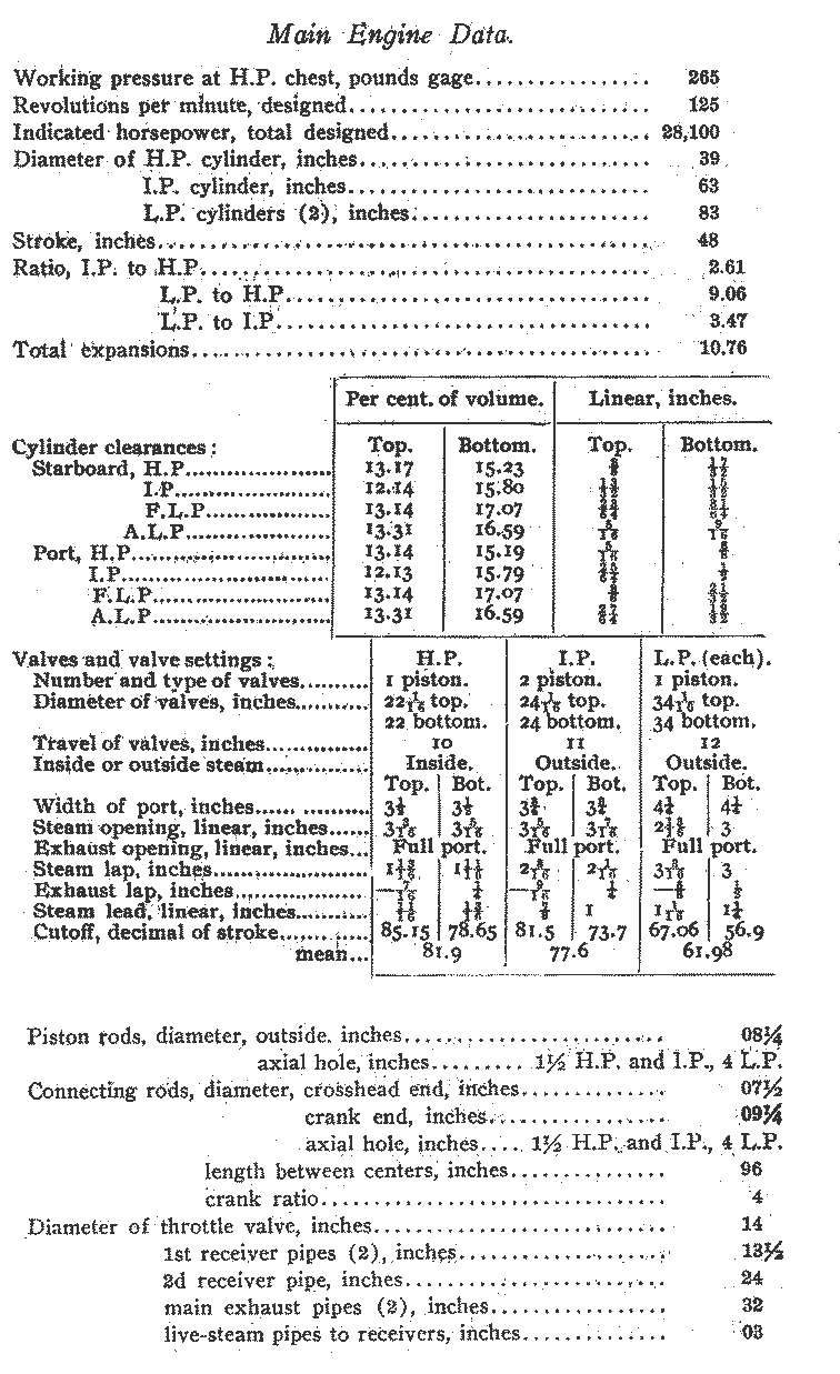
| Engine Data | ||
| February 1914 Journal of the American Society of Naval Engineers |
 |
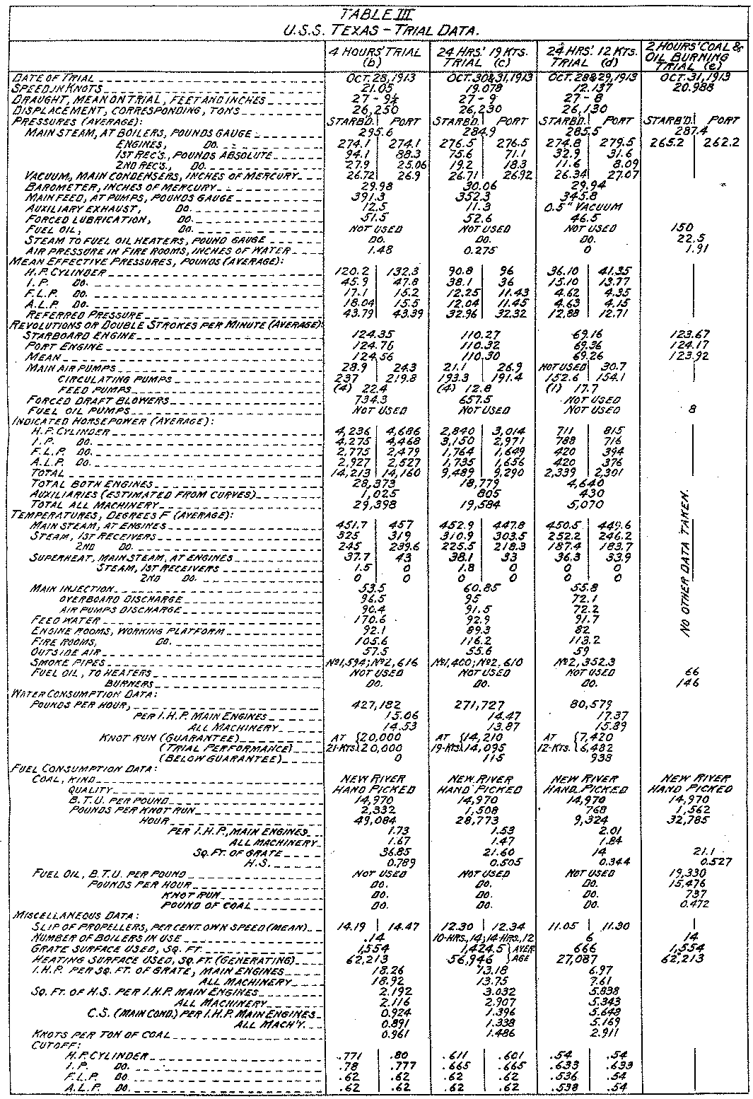
| Speed Trial Data: October 1913, Rockland, Maine |
| February 1914 Journal of the American Society of Naval Engineers |
 |
.
Started 11 May 1999 Chuck Moore, FTV (1st Texas Volunteers) BB35 volunteer group