.
.
| RADAR |
| While the capability of today's US Navy radar has
left TEXAS radar in the distant past, the fundamental principal in 1939 is still
the same that being a burst of energy is transmitted (TEXAS being radio and
microwave). When the energy strikes an object, some of the energy is reflected
back and and electronically displayed. |
|
| As of October 1944 |
| . | Install | Remove | A | S | Frequency (mhz) | Maker | Equipment Location |
| CXZ | Late 1938 - Jan 1939 | 1st qtr 1939 | X | . | 400 | RCA | Main deck - on wheels |
| CXAM-1 | Oct 1941 | Aug 1942 | X | . | 200 | RCA | Signal Bridge |
| SC-1 | Aug- 1942 | Feb 1944 | X | . | 200 | General Electric | Signal Bridge and Navigation Bridge Radio Rm Radar Plot-summer 1943 (renamed CIC) |
| SG | 1st unit - 1st qtr 1943 2nd unit summer 1943 | .. | . | X | 3000 | Raytheon | 1st unit: Navigation Bridge Radio Rm Radar Plot (renamed CIC)- summer 1943 2ND unit: Radar Room, 2nd deck - summer 1943 |
| SK | summer 1943 | ... | X | . | 200 | General Electric | Radar Room - 2nd deck |
| CXZ: Early 1939 |
| from 1947 RCA history "HOW RADAR CAME INTO BEING" |
In early 1939, two ship borne radar types were tested, CXZ on BB35 and XAF on BB34 with XAF had longer range CXZ had better definition. RCA took the best features of both and developed the next shipborne radar, CXAM |
| CXZ was developed by RCA in late 1938. The RCA unit incorporates the antenna and control together as one unit, mounted on wheels and located on the main deck | XAF Aboard New York the antenna mounted on foremast, above the Pilot House. Developed by the Naval Research Laboratories, XAF operated on 200 megacycles | ||
 |
 |
 |
 |
 |
| CXAM-1: October 1941 to August 1942 |
| CXAM-1, developed and built by RCA, incorporated
the better definition of their CXZ and longer range of the Naval Research
Laboratories unit XAF.
Initial contracts for production of six sets of CXAM
installed on USS California, Yorktown and four cruisers.
A second contract was let shortly afterward for an additional fourteen sets of a
slightly revised version known as the CXAM-1, one of which was placed on board
Texas in October 1941,Norfolk Navy Yard. When America
entered the war, these twenty sets were the only search radars in use by the
U.S. Navy.
Texas was the first ship in the Atlantic Squadron to have radar permanently
installed on board.
|
| CXAM-1 was replaced in August-October 1942 with SC-1 |
 Signal Bridge What had previously been the Flag Lieutenant’s Cabin on the port side of the Signal Bridge was modified into the new Radar Control Room where the transmitter, receiver and indicator of the CXAM-1, mounted together as one unit, were installed |
 1947 RCA history "HOW RADAR CAME INTO BEING" |
 |
 |
 |
 |
 |
 |
| SC-1: October 1942 to February 1944 |
| In August-October 1942, in Norfolk Navy Yard, CXAM-1 was replaced with Model SC-1, a new improved air
search radar built by General Electric. SC-1 was removed during the 23 January to 25 February 1944 period in the Boston Navy Yard. |
| Fall 1942 - summer 1943 SIGNAL BRIDGE - transmitter and receiver BRIDGE RADIO - radar indicator |
 |
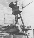
ANTENNA:
Large
square in the back of the photo. It was attached with a hinge so that it could
be folded over to pass under the Brooklyn Bridge |
||
| March 1943 - January 1944 SC-1 equipment relocated to the new CIC |
 |
| SG-1(1st unit): March 1943 - 1945 |
|
First (third operational radar aboard) installed 8 - 15 March 1943, Norfolk Navy Yard. Second in the summer of 1943.
Built by Raytheon, the Model SG utilized the multicavity type magnetron, a technological breakthrough developed by the British that allowed for the production of higher frequencies. The SG was the first US radar to operate within the microwave range, producing a 2 microsecond burst at a frequency of 3000 MHz. |
| The indicator was crammed in with the
SC-1 in Bridge Radio. The space was so crowded the radar operator had to step aside out of the main passage to allow others to pass between the bridge and the chart room |
||||
|
|
 |
| 23 January - 25 February 1944 |
| Boston Navy Yard, the SC-1 radar was removed and the SG antenna relocated to the top of the foremast. |
 |
 |
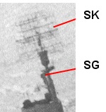
| SG (2nd unit) and SK |
| Summer 1943 |
| 2nd SG installed with antenna on the main mast The SK radar was installed at the same time The operating equipment for both located in the new "Radar Room Aux CIC", on 2nd deck. |
| As of summer 1943 |
 |
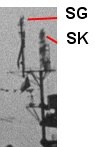
| September - October 1944 |
| SG antenna relocated above the SK antenna |
 |
 |
| RADAR II & AUX CIC - 2nd Deck |
 |
| Shortly after the 1943 construction of Radar Plot on board the Texas, the
print shop on the second deck was remodeled into radar room and auxiliary cic. The exact date is still unknown. Based on known photo
dates, the installation date was during a June 1943 stay in the Boston Navy Yard
or a mid July-mid August 1943 New York Navy Yard period. The space later doubled
as the auxiliary CIC. The space was outfitted with a second SG and a new air search radar called the SK. Adapted from the original CXAM and SC-1, the SK radar had a maximum detection range of 150 miles, earning a reputation as one of the best long-range air search radars of the war. The radars in this space remanded unchanged for the rest of the war. One of the key advancements of the Model SK radar was the addition of a plan position indicator (PPI). Earlier radars had utilized an A-scope on which the energy spikes were displayed, the length between the transmission spike and the return spike providing a distance to the target. While adequate for some applications, this method was at great disadvantage when tracking numerous pips. To solve this problem, the Naval Research Laboratory developed the PPI. This round display had a continuous sweep, synchronized to the rotation of the antenna, and portrayed all pips on the screen in relation to their position to the ship. |
| 1. Duplexing Unit for BL 2. Navigation table 3. BL Unit 4. Safety Switch - After & Emergency boards 5. Frequency range meter 6. TBS Speaker 7. Safety Switch - Fwd & After Boards 8. SK Transmitter 9. Tube Locker 10. Radar Power Panel 11. SK Dehydrator 12. 24MC Speaker 13. 20MC Speaker 14. Telephone & Communication Table 15. TBS Control Unit 16. Radar II Gear Locker 17. Vent System Exhaust 18. Air or Surface Plotting Table 19. Repeater Compass 20. Pitometer Log 21. Clock |
 |
21. Clock 22. BN 23 BL & BN Duplexing Unit 24. Magnetic Controller for SK 25. Motor Dynamo Amplifier Unit 26. 5 racks for spare parts boxes 27. SK 28. SK Supply Voltage Controller 29. Receiver Junction Box for SK 30. SK Gyro Switch 31. SK MG Switch 32. SG Supply Voltage Controller 33. SG Gyro Switch 34. Remote PPI Adapter 35. SG 36. SG Antenna Controller Unit 37. SG Lever Switch 38. SG MG Switch 39. Curtain Rod 40. SG Transmitter 41. Antenna Coax 42. SK Duplexer |
| The Radar Room underwent extensive restoration in 1993
-1994.
The photo is after the restoration. The SK unit is behind the chair and the SG is on the left. |
 |
.
Started 11 May 1999 Chuck Moore, FTV (1st Texas Volunteers) BB35 volunteer group